Linear Servo Motors in Parallel

With the Linear Servo Motor, you have the ability to drive two motors in parallel using only one encoder and one amplifier. All other systems require two drives, two controllers and two encoders, connected together. How is the Linear Servo Motor able to overcome these issues?
Nippon Pulse defines the parallel drive system as any application that has two or more linear motors in parallel. Parallel drive systems are most commonly thought of as being used in Cartesian/Gantry robots, though parallel drive systems also include other major areas of motion control.
High-precision and ultra-high-precision single axis robots
- These have a resolution and position accuracy in the sub-nanometer-to-high-picometer range. Optics Microscopes Semiconductor Machine Tool
Actuators where very high force is needed
- Material-testing equipment Punches
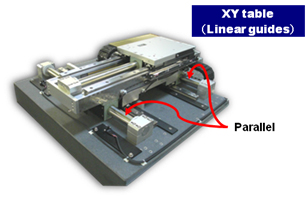
Cartesian/Gantry robots
- Pick-and-place work Glass cutters Application of sealant Assembly operations Handling machine tools Laser engravers Arc welding
 While this list is not all-inclusive, it shows applications in both the micron and submicron world. A parallel drive system can work in almost any industry.
See below for some of the issues that others have encountered when building a parallel drive system and how the Linear Servo Motor is advantageous when building your system.
Issues of Parallel Drive Systems
The major issue with all parallel drive systems (e.g., gantries) is orthogonal alignment (the ability to keep the parallel axis square). In mechanical driven systems (screw driven, rack and pinion, belt, and chain drive, to name a few) the main issue that arises is binding of the system due to misalignment or stacked up tolerances of the mechanical system. In direct drive systems there is an added issue of sine error that is introduced due to installation errors and variances in the linear motors themselves.
To overcome these issues, the common practice is to drive and control each side of the parallel system and electronically sync them. First, the cost of such a system is higher since it requires twice the electronics (drivers and feedback, etc.) when compared to a single-axis system. This type of tracking control system can also add synchronization and tracking errors, which adversely affects the performance of the system.
Advantages Offered by the Linear Servo Motor
Linear Servo Motors are highly responsive motors, and connecting them into a parallel system is easy.
 As with all parallel drive systems, the Linear Servo Motors must be physically coupled with a mechanism that, when applied, allows the axis to realize only one degree of freedom of movement. Since the dynamic motion generated by two identical Linear Servo Motors is the same when they are given the same control signal, the asynchronous motion of the above-described parallel system is inevitable. This, in effect, makes it possible to operate the system with a single encoder and single servo driver.
The Linear Servo Motor is a non-contact system; when installed properly, it is impossible for it to introduce any mechanical binding into the system, due to the air gap.
Air Gap
One advantage of the Linear Servo Motor over other non-contact linear motors is that the design of the Linear Servo Motor – with the magnet in the center – makes the air gap non-critical. The coil completely surrounds the magnet, so force is the net effect of the magnetic field. This does away with any force variations that would have been caused by air gap differences, such as alignment or machining differences, allowing alignment and installation of the motor to be very simple.
What is Sine Error?
Sine error is the force differences that are produced due to misalignment of a motor’s coils or magnetic tracks.

In linear motors, current is applied to the coil to form an electromagnet. The coil then synchronizes itself to the magnet field generated by the permanent magnets in the magnet track. Force is generated due to the relative strength of these magnetic fields and the angle of their intentional misalignment.
In a parallel drive system, when the magnetic fields to all the coils are perfectly aligned and all the magnetic fields in all the magnetic tracks are perfectly aligned, they become – in effect – a single motor without any differences of force generation. However, any misalignment of the coils or magnetic tracks will cause the angle of misalignment of the magnetic fields in the motors to differ from one another, producing different forces in each motor. This force can, in turn, cause binding in the system.
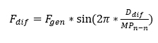
Sine error can be calculated by the following formula:
Where:
Fdif – Force difference between the two coils
Fgen – Force generated
Ddif – Length of misalignment
MPn-n – North to North Magnetic pitch
Most linear motors are designed with a north-to-north magnetic pitch in the range of 25 to 60mm long under the guise of trying to reduce IR losses and the electrical time constant. So, for example, a misalignment of just 1mm in a linear motor with a 30mm N-N pitch will cause a loss of about 21 percent of its power.
On the other hand, the Linear Servo Motor uses a much longer north-to-north magnetic pitch in order to reduce the effect of sine error due to accidental misalignment. Therefore, the same misalignment of 1mm in a Linear Servo Motor with a 90mm N-N pitch will only result in a 7 percent loss of power.
Parallel Drive Systems Summary
Truly accurate positioning is only possible when the feedback is directly in the center of mass of the work point. You also want your force generation from the motor right in the center of the mass of the work point.
By putting an encoder in the center of mass – and using parallel Linear Servo Motors equally spaced off the center of mass – you are getting the desired feedback and force generation in the center of mass. This is impossible for other types of parallel drive systems, which require two sets of encoders and servo drives to provide parallel functionality.
It is possible to connect any number of Linear Servo Motors, thus allowing their forces to be added together. Regardless of the number of parallel axes, you will only ever need one driver, one controller and one encoder.
Examples of Parallel Linear Servo Motor System
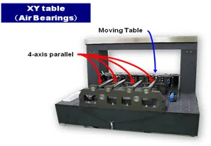
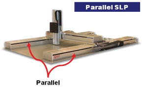
Points to keep in mind when designing and putting together a parallel Linear Servo Motor system
1. Physically Connecting Motors
The forcers and shafts in a parallel drive system must be physically coupled with a mechanism that, when applied, allows the moving axis to realize one-degree-of-freedom movement.

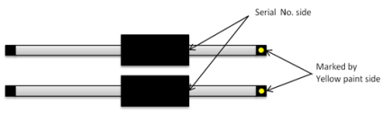
2. Motor Installation and Orientation
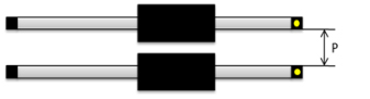
Both forcers must be oriented in the same direction on their shafts. It is suggested that the end of the forcer that has the serial number be pointing toward the end of the shaft that is marked with yellow paint. If the orientation of the coils is different, it is possible to have a totally inoperable or a runaway system, or it will cause significant loss of thrust. The standard for parallel drive system is mirrored cable exit locations. See drawing below.
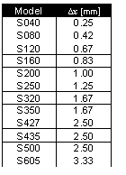
3. Deviation in mounting the motor
To minimize loss of thrust due to sine error, it is recommended that the mounting position difference between the Linear Servo Motors [Δx= Δx1- Δx2] be less than the values shown on the table below.

4. Motor Spacing
It is recommended that the minimum spacing (P) between the parallel shafts be maintained as shown in the table to the right. If the shafts are installed closer than what is shown in the table to the right, it is possible to warp the shafts due to magnetic interference.