Linear Motor Systems: Iron Core, U-Channel, and Tubular Linear Motors
Introduction:
There are three main direct drive linear motion systems on the market today. These three motor types have distinct advantages and disadvantages and, based on the application, one motor will be better suited than either of the other motors. This white paper will present the basic mechanism of operation of these three linear motors along with the advantages and disadvantages of each. The three linear motors that will be presented are Iron-Core, U-Channel, and tubular linear motors. Each motor has a different form factor, achievable force density, and efficiency that sets them apart from the others. Understanding the differences between these motor types will give the designer the ability to choose the motor that best fits the application, instead of choosing the most familiar motor by default.
Motor Types:
Iron Core Motor
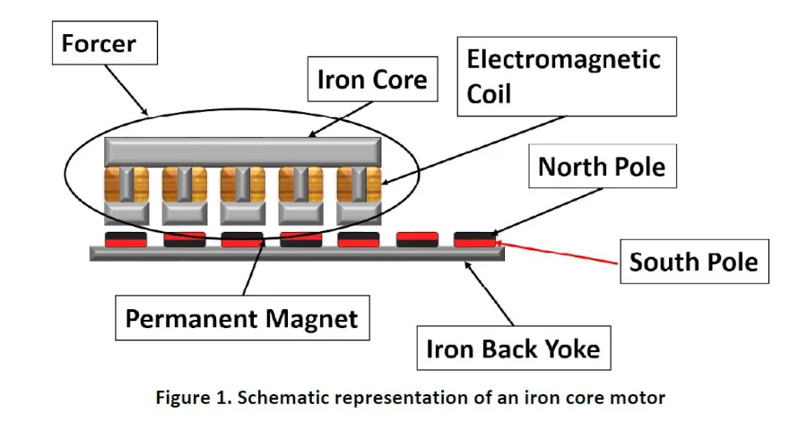
As the name suggests, iron core motors have iron in the motor. This motor is probably the best-known linear motor and has been around for a long time. The basic structure of the motor is similar to an unrolled rotary motor with discrete stator and magnetic poles. As the old saying goes, a picture is worth a thousand words, so a schematic representation of an iron core motor is shown below. As seen in the figure, the motor has a set of electromagnetic coils that are wrapped around an iron core. The end effect of this is to increase the amount of magnetic field generated by the coils, as the iron will contribute to the generated field through realigning of microscopic magnetic domains in the iron so they are in line with the magnetic field from the coils. Since magnetic fields are vector quantities, direction and intensity are additive and result in a substantial increase in the field strength seen by the track magnets. This is the major advantage of the iron core motor in that for a given input of current, there is a significant amount of force that can be generated due to this behavior.
The iron core motor does have some disadvantages or, at the very least, behaviors that need to be taken into consideration when designing a system that uses this motor type.
- Cogging – This is a significant design concern if the system requirements include smoothness of motion. Cogging is the movement of the motor’s iron forcer so as to align itself with the magnetic poles of the permanent magnets, due to the attractive forces created by the induced magnetic fields in the iron by the permanent magnets. Cogging is present in all motors (rotary or linear) that use iron for the stator and permanent magnets.
- Eddy currents and heat – The use of time-varying magnetic fields, such as in an electric motor that has significant metal content, will create eddy currents. This is a consequence of the basic physics of the interaction of the changing magnetic fields and the metal. These eddy currents have a couple of impacts on the motor operation. The first is the creation of an opposing magnetic field to that created by the electromagnetic coils, and the second is the generation of heat in the iron components due to resistive heating by the current flow in the metal. While iron core motors manufactured today take steps to reduce eddy current production, they cannot be eliminated altogether.
- Magnetic saturation – The source of the large force generation of the iron core motor also creates a challenge in operation when pushing the generated forces outside of the normal operating range. The reason that the iron core motors are able to generate the force they do is because the iron in the motor has magnetic domains that reorient to the magnetic fields created by the coils. This adds to the intensity of the magnetic field and thus the force generated. As the fields from the coils get larger, more of the domains line up until all of them are in line. At this point the iron has reached magnetic saturation and the force-to-current relationship changes and becomes non-linear, making control more difficult.
- Large footprint – The basic construction of iron core motors leads to the motors having a fairly large footprint. The permanent magnets that are used in the motor are laid out so that either the north or south pole is facing toward the forcer. This requires the magnets to be larger – either wider or longer – in order to increase the amount of force generated as only half of the magnetic flux from the motor is utilized in generating force.
- Lateral and attractive (non-useful) forces – The attractive force that exists between the iron core and the permanent magnets can be significantly greater than the amount of force that is created when the motor is energized. This force will pull the forcer toward the magnets and requires the linear guides to be more robust than for other linear motors. This situation also creates lateral forces that would move the forcer off the track if allowed. This also requires the motor design to have additional constraints put in place to resist these lateral forces.
While there are several items that need to be taken into account by the designer of a linear motion system during the design process, the large force generation of the motor for its size can and does outweigh the other factors, making it the motor of choice.
U-Channel Motor
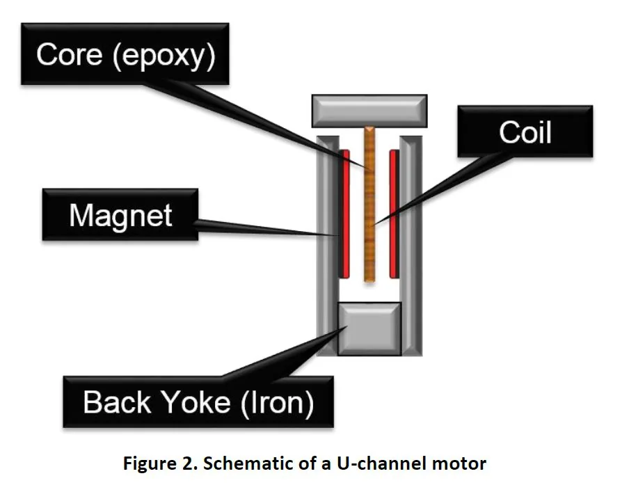
U-Channel motors were designed to have a direct drive linear motor without some of the behaviors of the iron core type motors. One of the main features of this motor is the absence of iron from the critical locations in the motor. This eliminates cogging and the non-linear relationship between the force and current due to magnetic saturation. In order to increase the amount of force generated by the motor, an additional set of permanent magnets has been added to the motor in a double-sided configuration. Additionally, the forcer is made with the electromagnetic coils that are epoxy-mounted to the non-ferrous forcer plate, typically made from aluminum. A schematic of a U-channel motor is shown below in Figure 2, where the double-sided configuration can be identified.
As with the iron core motor, the U-channel has advantages and disadvantages that the designer will need to consider when selecting a motor. This motor type typically has a rectangular structure and can be mounted in either a vertical or horizontal orientation, depending on the space constraints. The motor can have a low flat profile to fit in limited-height spaces. The other advantage of the U-channel motor type is the absence of cogging. As with all things, there are a few disadvantages that are present in the U-channel motor.
- Lower stiffness – With the coils attached to the forcer via an epoxy molding, the inherent stiffness of the motor is significantly less than for the other two motor types. This has its origin in the material stiffness of the epoxy and of the shape factor of the electromagnetic coils. In order for the coils to interact with the permanent magnets, the orientation of the coils presents a weaker direction of the shape to the direction of force generation. This reduced stiffness is one of the reasons for the reduction of the force output of the U-channel motors over iron core motor.
- Reduced heat dissipation – With the removal of iron from the magnetically operational areas of the motor, a second row of magnets is added to increase the force output of the motor. In order to have this second row of magnets, a U-channel structure is employed. The use of the U-channel along with the coils residing inside during operation reduces air flow in the area where the heat is generated – the coils. Additionally, the epoxy mounting mechanism has very low thermal conductivity in comparison to iron. The result of these two factors is reduced heat transport. This low heat transfer many times requires the addition of a heat sink to control the heat buildup in the motor.
- Lower operational temperature – The low heat transfer of the motor from the areas that produce the heat limits the operational envelope of the motor. This is due to the mounting of the coils. As a class of materials, epoxies and plastics have low operational temperatures. While they may not start to combust at temperatures that are common to other motors, they will lose a significant amount of the material strength and stiffness at these elevated temperatures. In order to maintain performance and the integrity of the motor, the operational temperatures of U-channel motors are lower than the other linear motor types.
- Higher cost – The expense of the second set of magnets needed to increase the force output increases the costs.
The advantages and disadvantages of the U-channel motor make its selection specific to a set of conditions; when one is selected for these conditions, it will do well. Would the other motors work with these conditions? Maybe, but not as well, and other design sacrifices may need to be made.
Tubular Linear Motor
Tubular linear motors are a departure from the design approach of the previous two motor designs. Instead of having the electromagnetic coils interacting with the permanent magnets by riding over flat magnets, the tubular linear motor has the coils surrounding disk-shaped magnets. The orientation of the magnetic poles of this magnet shape creates a magnetic flux 90° relative to the coils. In order to understand the construction and orientation of the important operational parts of the motor, a schematic representation of a tubular motor is presented in Figure 3.
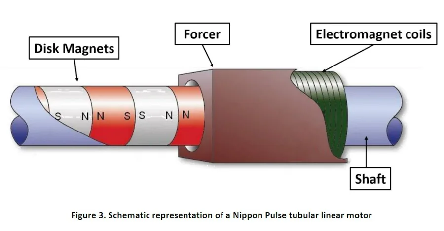
As can be seen in the figure, the tubular linear motor coils completely surround the magnets and thus will utilize all of the magnetic flux of the permanent magnets. The forcer is constructed so that the current that is injected is adjusted across the three phases so that the magnetic field distribution is distributed within the forcer, so as to line up with the poles on the shaft. The magnetic field distribution can be infinitely varied within the forcer, and provides exceptional positioning control. The utilization of the all of the magnetic flux improves force generation efficiency while keeping the costs low in comparison to the other two linear motor designs. Tubular linear motors are not capable of generating the forces of the iron core motor, but they also don’t have to contend with the other attendant problems of that motor design. There is no cogging, non-useful forces, non-linear force-to-current relationships, or eddy current generation due to the design of the motor. A comparison of the tubular linear motor design and iron core motors is listed in the table below.
Compared to an Iron Core Motor
| Iron Core | Tubular | ||
|---|---|---|---|
| Advantages | Disadvantages | Advantages | Disadvantages |
| High force generation | Cogging | Smoothness | Lower force generation |
| Good heat dissipation | Attractive and lateral forcers | Easy integration | |
| Well known | Eddy currents | Efficient cooling | |
| Magnetic saturation | Linear force-to-current relationship | ||
| Large footprint | Compact design | ||
While the forcer completely surrounds the magnets in the shaft, the movement of the forcer over the shaft and a non-critical air gap, in the case of Nippon Pulse’s Linear Servo Motor, provides more efficient cooling than the U-channel motor type. The tubular linear motor forcer also benefits from a greater stiffness than the U-channel motor, due to the strong direction of the coil cylindrical geometry in the direction of force generation. A comparison exists in the table below.
Compared to a U-Channel Motor
| U-Channel | Tubular | ||
|---|---|---|---|
| Advantages | Disadvantages | Advantages | Disadvantages |
| No cogging | Inefficient cooling | Efficient cooling | More height |
| Well known motor technology | Low stiffness | Excellent stiffness | |
| Large footprint | Compact design | ||
| Higher cost | Lower cost | ||
Conclusion:
Understanding the differences between linear motors is necessary to get the best performance out of a system and to achieve the machine objectives. Each motor type has its place where it performs better than the other motors. Iron core motors are great mass movers due to the forces they generate, but they’re not good at smooth and precise motion due to cogging. U-channel motors provide smooth motion at lower force ranges but have difficulty with dissipation of heat when used hard. Tubular linear motors overcome a lot of the disadvantages of the two other motor types, but aren’t as well known. Many view the tubular linear motor as a replacement for pneumatic cylinders, but they can be so much more than just that. Nippon Pulse Linear Servo Motors have been used in high force applications and high resolution-high accuracy applications. The ability of this motor technology to be so versatile is a good motivation to explore and understand this newer motor technology for your next application.
