Building a motion control system: Limit switches and circuit considerations
By Jerame Chamberlain and Allie Kuester
Every motion control system will have specific limits where motion should occur. These limits are used to specify the range of motion to prevent damage to the machine itself, or personnel operating the machine. When a motion system has a specific “safe” range of motion, limit switches are often used to restrict the motion to keep it in the safe range.
Limit switches are typically a mechanical or solid-state device that sends a signal to a motion controller that the motor has reached its safe end of travel. They are used primarily in linear motion systems, but can be found in rotary systems as well.
Manufacturers typically use built-in limit switches in linear stages like the NPM SCR precision stages, with the switches integrated into the encoder. Options are also available to add limit switches as required to meet specific requirements, such as homing, or “slow down” zones.
Limit switches are used in applications such as pumps (to indicate the fluid has finished moving from its original location to the new one) and for safety interlocks (to ensure the system stops when an interference is introduced).
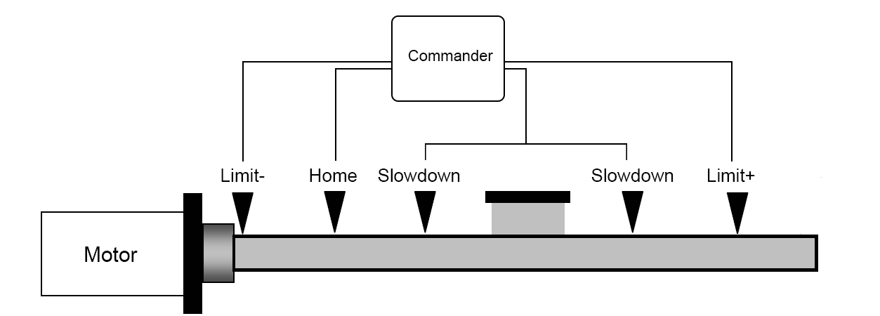
For safety, end limits and slow down switches are a good idea in any linear motion system. It is important to place the positive limit at the end of positive travel, and negative limit at the end of negative travel. When the limit switch becomes active, the motion controller should immediately stop movement in that direction, though movement will still be allowed in the opposite direction.
When designing your limit circuit, here are a few things to keep in mind:
- 1) The motor MUST stop when the limit signal is active for the direction it is traveling.
- 2) Ensure your limits do not trigger due to electrical noise. Random limit errors can stop your motion control system and cause inefficiencies.
- 3) If the cable connecting the limit switch to the controller becomes disconnected, the limit signal must trigger as active to stop movement in that direction. This would alert the user to the connection issue.
These three points can help you when thinking about the limit circuit and active logic level in your motion control system.
Nippon Pulse has controller options with mechanical limits for each axis, including our Commander core, which offers soft limits for deceleration of the movement before it stops; this function can be used in addition to or instead of limit switches.