
Nippon Pulse to attend November's Smart Production Solutions tradeshow
Sep 29, 2023
Nippon Pulse is once again excited to partner with Dynetics GmbH to bring our products to the SPS (Smart Production Solutions) show in Nuremberg this fall.
Sep 29, 2023
Nippon Pulse is once again excited to partner with Dynetics GmbH to bring our products to the SPS (Smart Production Solutions) show in Nuremberg this fall.
Aug 22, 2023
Nippon Pulse is excited to share that we will be showcasing our servo motor product lines at the Motek tradeshow, alongside our distributor Dynetics GmbH.
Aug 18, 2023
Our latest models are the lightweight yet powerful MDx series of direct-drive AC servo motors, perfect for factory automation, semiconductor, life science, security, and haptics applications.
Aug 10, 2023
Nippon Pulse is pleased to introduce a new series of motors to its extensive line of Linear Shaft Motor servomotors. The SX series features high-energy magnets for greater force in mid-range sizes, to supplement the existing sizes of the standard S-series motors.
Feb 07, 2023
Nippon Pulse is excited to introduce a new podcast, where our engineers will be sharing some of their motion control expertise in a short, easy-to-listen format!
Dec 09, 2022
Nippon Pulse America Inc. has been invited to exhibit with our customer ASC International Inc. at the IPC APEX EXPO tradeshow in early 2023. ASC and Nippon Pulse will be in booth #827.
Sep 15, 2022
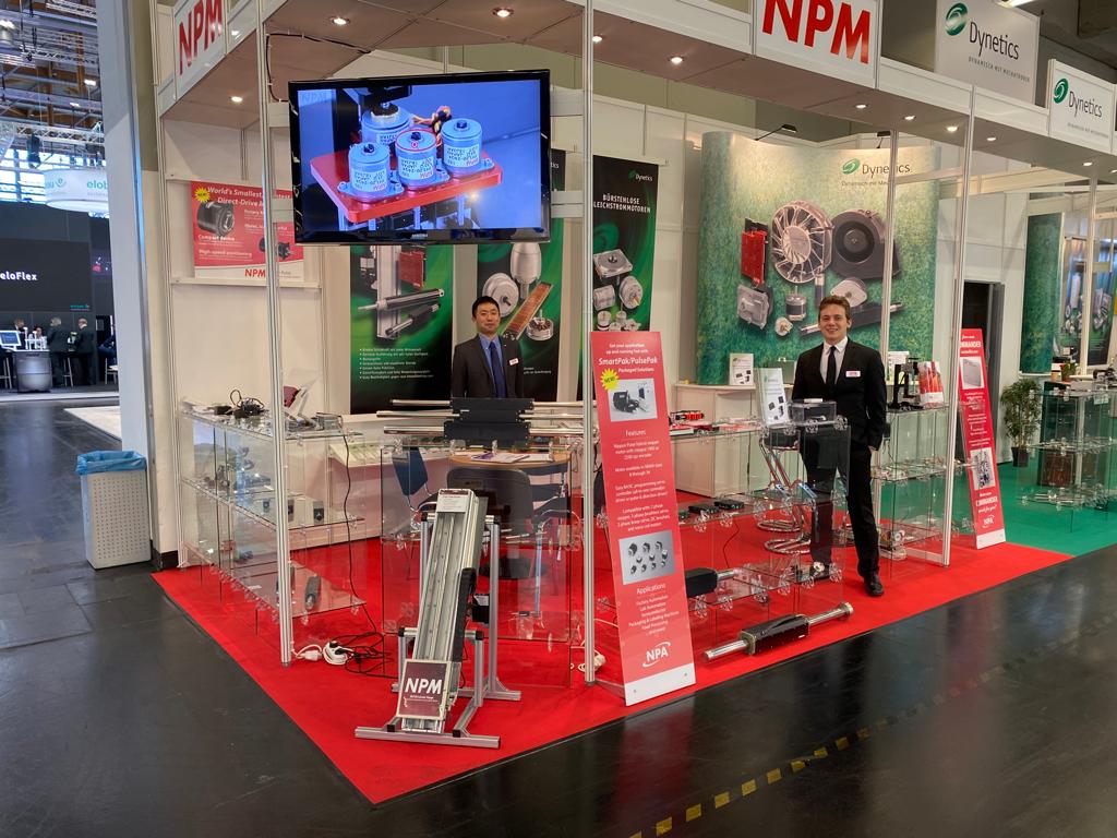
Nippon Pulse is honored to collaborate again with our distribution partner Dynetics for the 2022 Smart Production Solutions tradeshow. SPS will be taking place in Nuremberg, Germany, from November 8-11, 2022 -- a couple weeks earlier this year than in previous years.
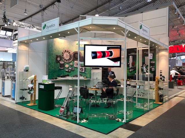
Sep 13, 2022
Nippon Pulse is excited to be showcasing some new demos at the Motek tradeshow in October, in collaboration with our German distributor, Dynetics GmbH.
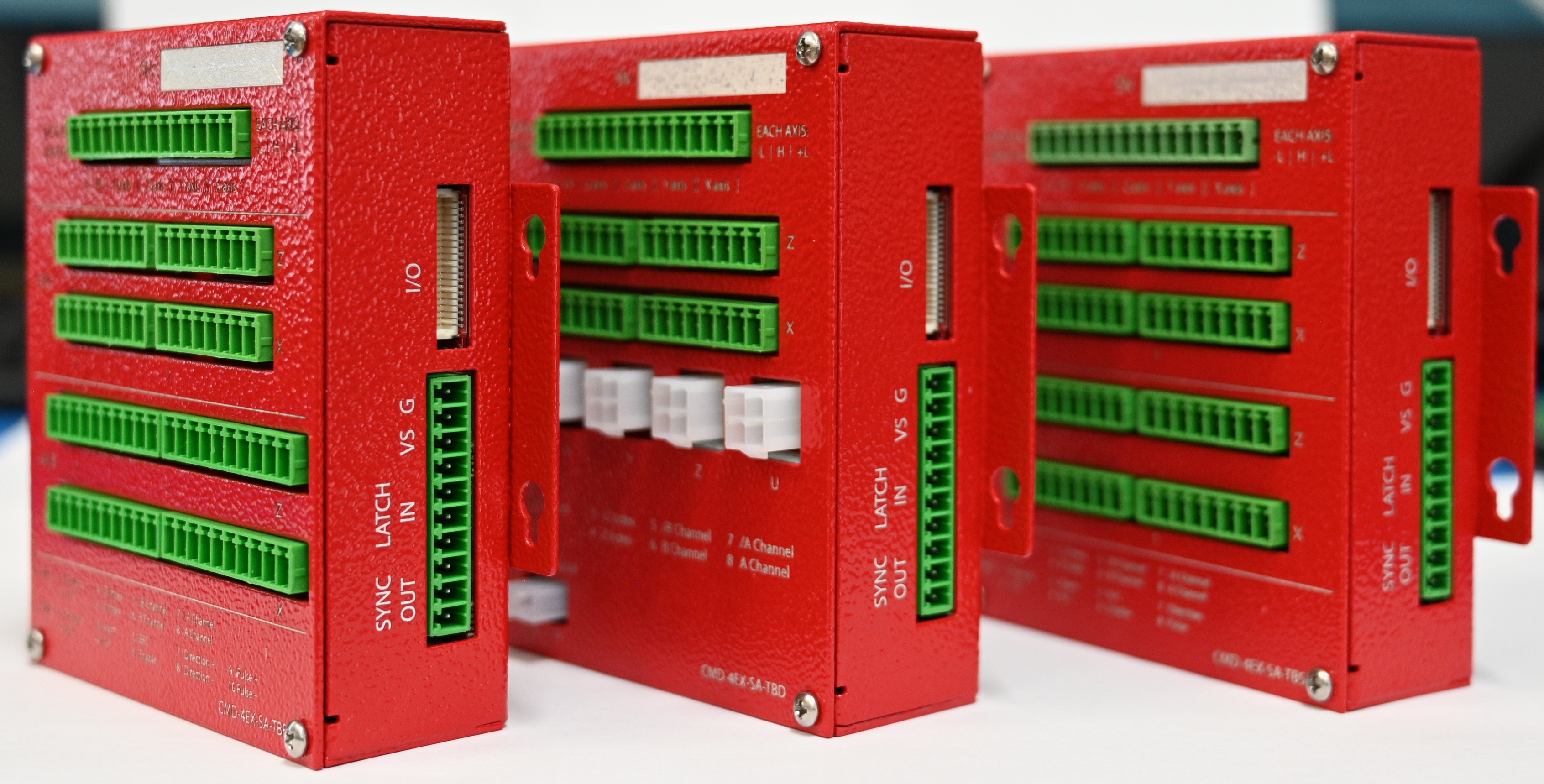
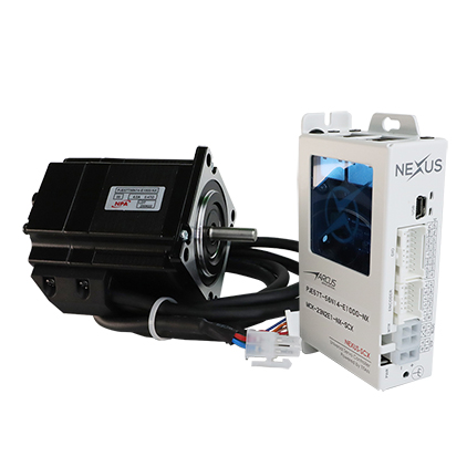
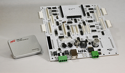
Jun 21, 2022
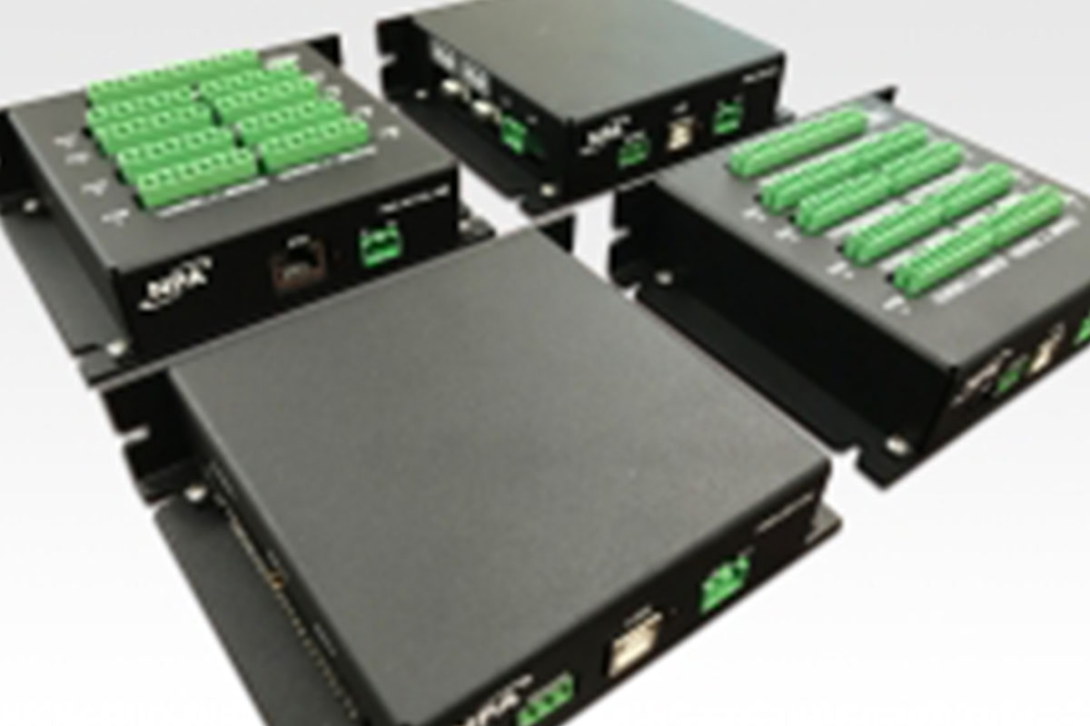
Nippon Pulse is excited to announce its new generation of box-level motion controllers, the Commander box (CMD-4EX). The CMD-4EX controllers contain a Nippon Pulse Commander core module (CMD-4CR), which provides some new features for our box controllers, as well as improvements to features of the first-generation PMX box controllers.
Apr 11, 2022
Nippon Pulse America, Inc. will showcase Linear Shaft Motor servomotors, rotary servomotors, and robotics that feature agile movement and fine positioning, at the largest automation show in North America.
Jan 12, 2022
Nippon Pulse has recently made select products available on engineering component websites Digi-Key and Allied Electronics & Automation. We are excited to announce that you can now access "buy now" links direct from specific products on our website. We hope this will make it easier for our customers to purchase some of our standard motor and controller products.
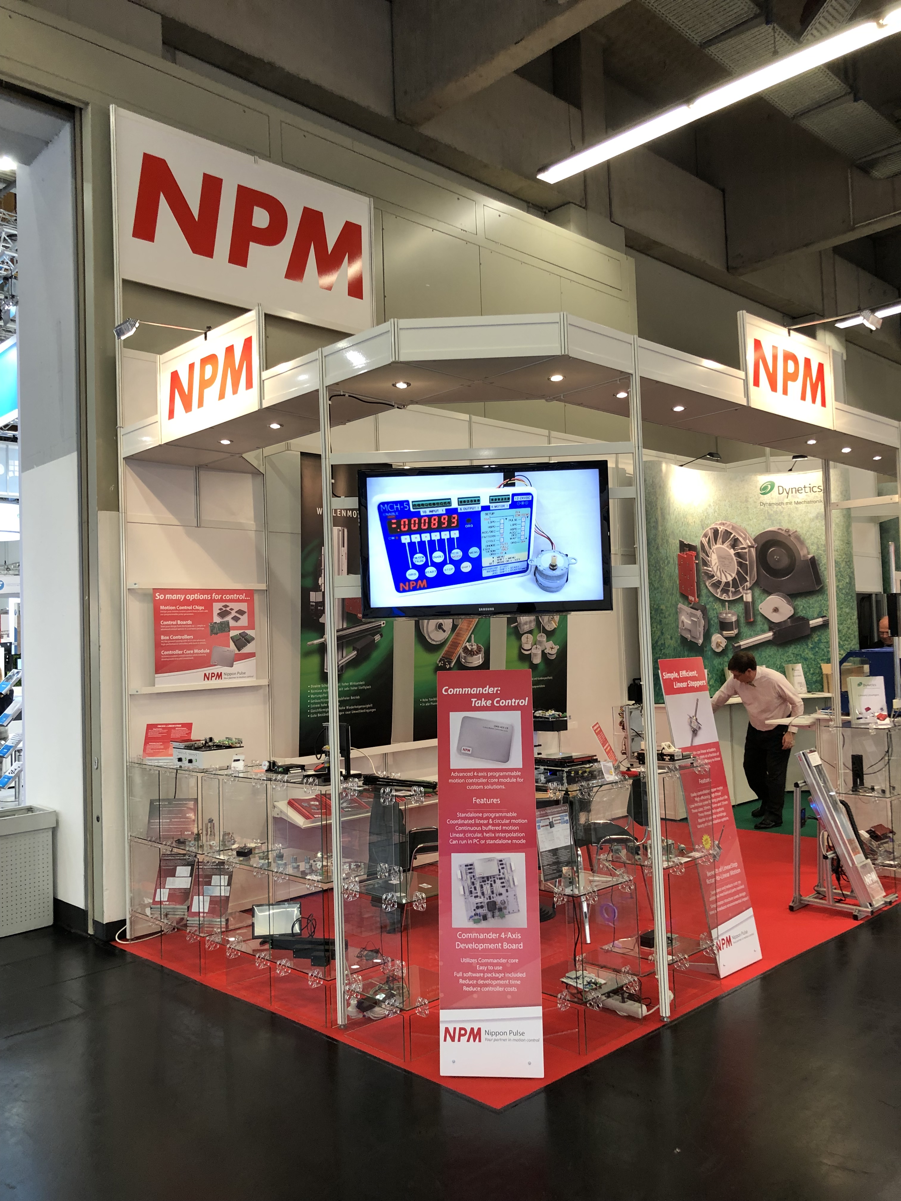
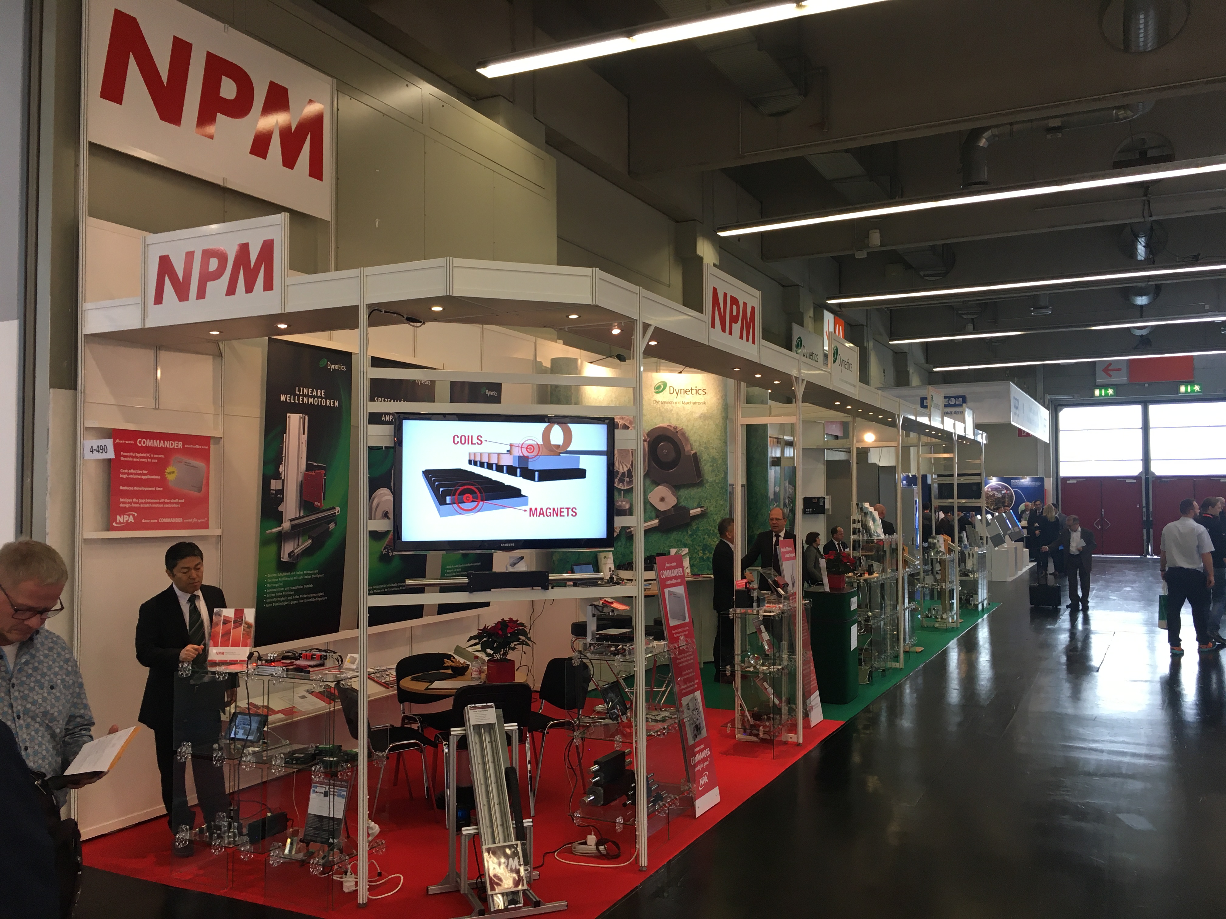
Nov 09, 2021
Nippon Pulse will be present at the Smart Production Solutions (SPS) 2021 exhibition in its first in-person event in over a year! Our booth will be in Hall 4, Booth 490, alongside our German distributor, Dynetics GmbH.
Jul 21, 2021
Nippon Pulse has introduced two new pre-packaged motion control solutions to help get stepper motor applications up and running fast: the SmartPak and PulsePak motion controller kits. Each kit contains a hybrid stepper motor with an integral encoder, a servo controller, and a cable kit to connect everything together.
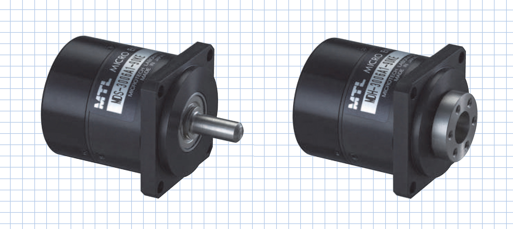
Sep 01, 2020
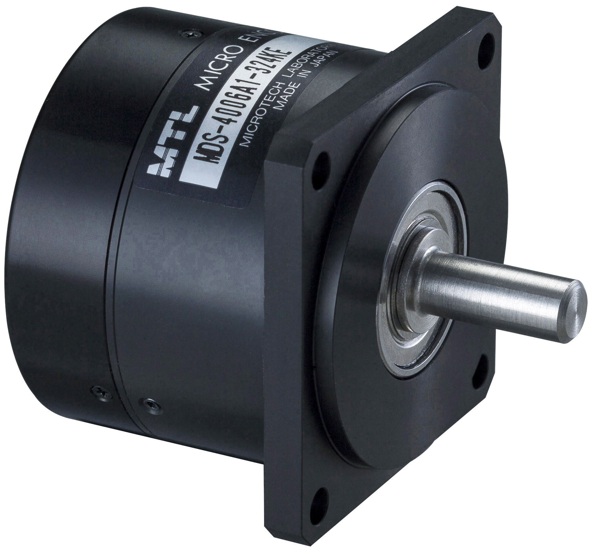
Nippon Pulse America, Inc. is pleased to introduce its new series of high-performance micro direct-drive AC servomotors. These servomotors are available in frame sizes as small as 13mm and as large as 70mm, and can support hollow shaft structures. Each frame size is available in three stack lengths to fit into your application's space requirements. The motor and encoder are integrated into a single compact unit.
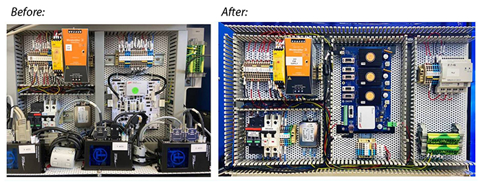
May 22, 2020
Nippon Pulse is pleased to offer a new service for our OEM customers: the creation of custom-designed motion controller boards that utilize the Nippon Pulse Commander core for multi-axis applications. The boards can be designed to meet unique specifications, helping streamline the design process to bring a new product to market faster or reduce the manufacture/testing time on an existing product.
Mar 03, 2020
Nippon Pulse is introducing a Commander evaluation kit to help original equipment manufacturers reduce development time and investment, and ramp up production of their applications. The evaluation kit utilizes the Nippon Pulse Commander core - an easy-to-use four-axis hybrid IC motion controller - and full software package for application development.
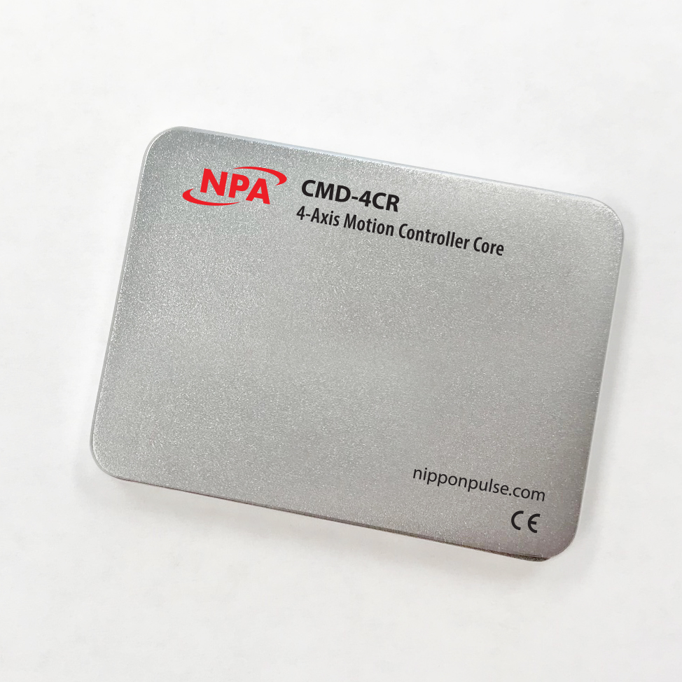
Jan 22, 2020
Nippon Pulse America, Inc., is pleased to introduce its new Commander core motion controller, a four-axis hybrid IC that bridges the gap between off-the-shelf and design-from-scratch controllers. The Commander core is secure, flexible and is easily scalable from prototype to production while remaining cost-effective for high-volume applications.
May 31, 2019
Nippon Pulse is pleased to announce its new PJE series of bipolar hybrid stepper motors, which are available in sizes from 20mm to 86mm in diameter (NEMA sizes 8-34).
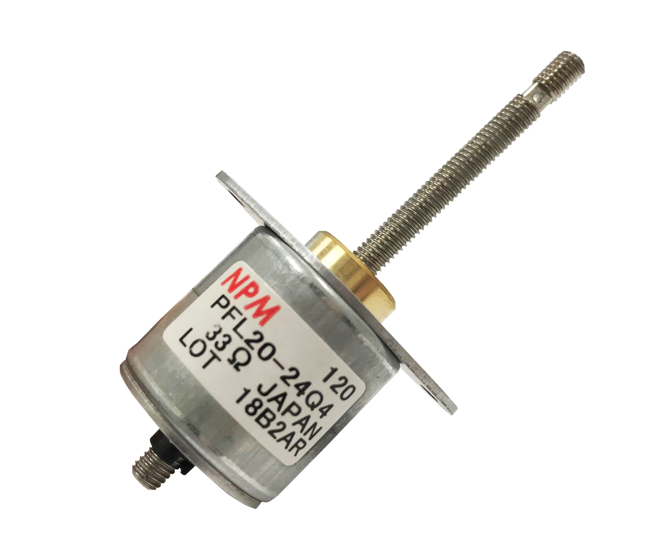
Mar 20, 2019
Nippon Pulse is excited to introduce its smallest linear stepper motor yet, the PFL20 Linearstep. The PFL20 is a highly efficient, high thrust tin-can linear actuator with a 20mm diameter and a bipolar winding.
Jul 09, 2018
Nippon Pulse America, Inc. (NPA) is thrilled to offer our customers even more quality motion control products with its acquisition of Arcus Technology's Performax (PMX) motion controllers. PMX box controllers utilize Nippon Pulse's PCL6000 series advanced motion controller chips for 4-axis and 2-axis motion.
Jun 19, 2018
Nippon Pulse America Inc. (NPA) has recently received upgraded international standards certificates for its combined Quality Management and Environmental Management systems.
Sep 20, 2017
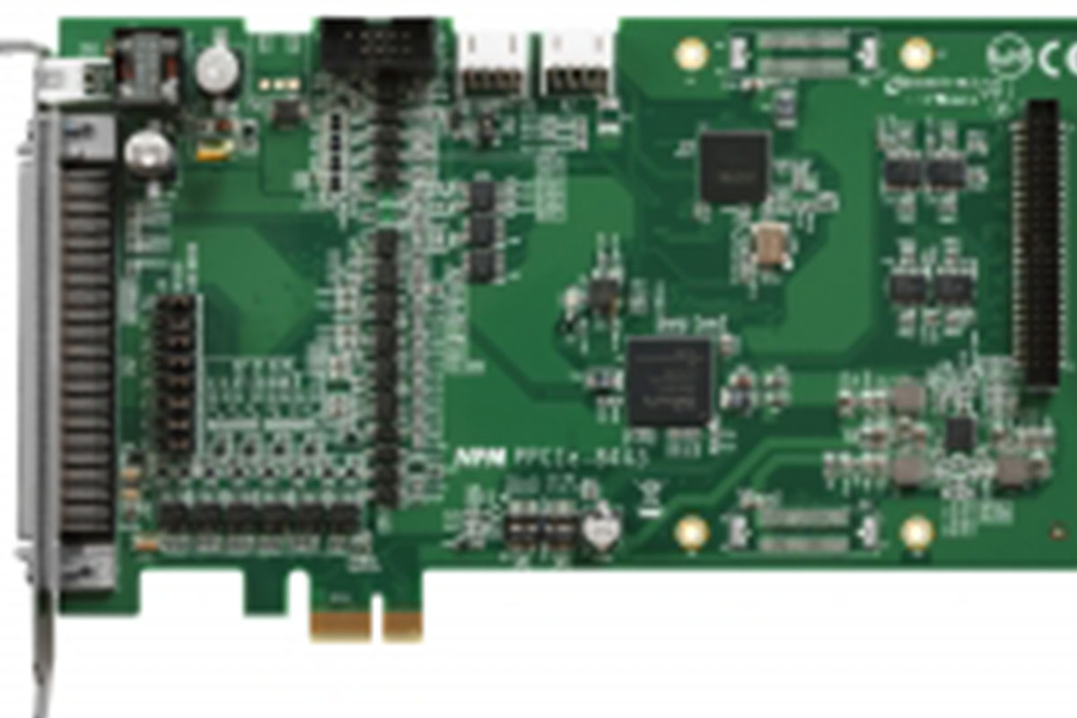
Nippon Pulse is excited to introduce its newest available controller board, the PPCIe8443. An upgrade from Nippon Pulse's previous PPCI7443 controller board, the new "PCI Express" board utilizes an updated PCI-express bus interface that can control up to 4 axes of coordinated motion.
Jun 13, 2017
Nippon Pulse's PCL6000 series of chip-level controllers have long been available with highly advanced features, making them the most advanced controller chips in the world. In addition to their standard linear and circular interpolation options, two of our advanced controller chips now feature a third interpolation option: spiral, or helical, interpolation.
Mar 14, 2017
Nippon Pulse America Inc. is excited to introduce one of the smallest available linear motors for high-density applications, the L250SSS Linear Shaft Motor. It is a 25mm diameter linear servo motor with a single winding and our smallest available forcer - only 30mm in length, and with higher force than competing off-the-shelf motors.
Jun 20, 2016
Nippon Pulse is pleased to announce that more than 10 new CAD models for the company's tin-can and hybrid stepper motors are now available for download.
May 23, 2016
Nippon Pulse is pleased to announce a collection of new datasheets for its large-air-gap L series and short-forcer SS series Linear Shaft Motors. These datasheets are for motors that are 25mm, 32mm and 35mm in diameter, all of which have several alternate windings available to meet performance and voltage requirements.
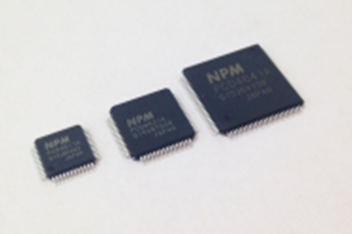
Apr 25, 2016
Nippon Pulse has released a new line of PCD controller chips as an upgrade for the PCD46x1 series. The new 46x1A series includes updates that fix bugs from the 46x1 series, and offers a few new features as well.
Apr 04, 2016
Nippon Pulse America Inc. (NPA) is pleased to announce that its Virginia-based sales office has been approved for ISO 9001:2008 and 14001:2004 certifications by BSI America.
Jun 09, 2015
Nippon Pulse is pleased to announce that updated datasheets are available for the Linear Shaft Motor S series servomotors.
Jun 02, 2015
PJPL linear hybrid motor ideal for medical, lab applications RADFORD, Va. - Nippon Pulse's PJPL Series motor is a series of two linear hybrid stepper motors. This series is ideal for motion control applications where the benefits of a smaller motor size with high force capabilities are essential.
Feb 26, 2013
NIPPON PULSE OFFERS GEARED STEPPER TO REPLACE NEMA11 PFCU30 w/ Integrated Gear Produces 100mNÂm of Torque, Replace NEMA11 Hybrid RADFORD, VA -- Nippon Pulse has introduced the PFCU30 integrated geared stepper motor as a replacement option for a NEMA11 hybrid stepper motor. Because it is a tin-can style stepper motor, the PFCU30 is available at a much lower cost than a NEMA11 hybrid stepper motor, potentially 50 percent lower.
Jan 23, 2013
Nippon Pulse has introduced the PFC10 rotary tin-can stepper motor, the company's smallest rotary motor to date. The motor has a 10mm diameter, 10mm smaller than the previous smallest motor. A permanent magnet motor, the PFC10 tin-can stepper is a fit for small medical device applications, fluid dispensing, valve control, gaming machines, and other applications requiring a small rotary motor solution.
Oct 25, 2012
Nippon Pulse has introduced four new driver boards for use with 2-phase stepper motors. Now available are the AD1111, AD1131, AD1231, AD1431 to drive bipolar and unipolar stepper motors. All four drivers are ideal for integration into systems or for use during prototyping and evaluation phases.
Apr 18, 2012
For accurate and precision positioning, Nippon Pulse offers its PFCL25 linear stepper motor. Nippon Pulse's linear stepper motors provide a cost effective solution to designers who need direct linear motion. Easily integrated into applications, the Nippon Pulse linear stepper motors simplify conversion from rotary to linear motion.
Mar 28, 2012
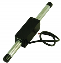
Available from Nippon Pulse is its S605 Linear Shaft Motor (linear motor) which offers up to 3100N of acceleration force and a continuous force of 780N. The S605 Linear Shaft Motor is ideal for industrial applications requiring high force, high precision, energy efficiency, and/or high precision. The motor, because of the simple nature of its structure can achieve sub-micron resolution.
Dec 13, 2011
The Nippon Pulse PFCU20 tin-can style stepper motor offers users high torque in a small package (20mm diameter), using an integrated reduction gear to achieve up to 10mN�m of holding torque.
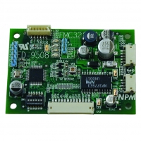
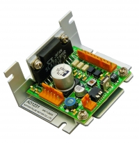
Nov 22, 2011
Nippon Pulse has announced the release of its newest motion control product, the FMC32 control board for control of 2-phase bipolar stepper motors. The FMC32 is a compact controller with an integrated driver and is equipped with the LSI PCD2112 chip for controlling a serial bus.
Aug 09, 2011
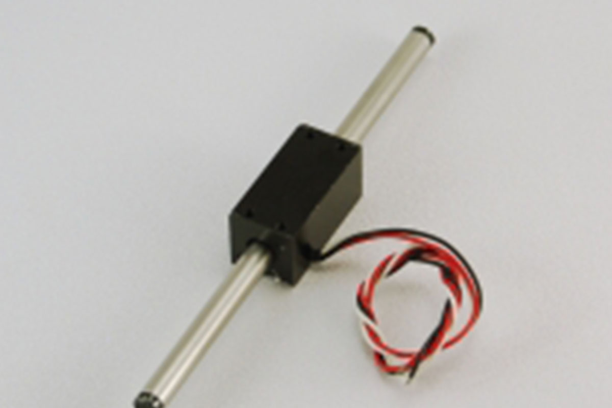
Available from Nippon Pulse is the 4mm Linear Shaft Motor (model S040), a servomotor designed for small-scale, high-precision applications. The smallest in the Linear Shaft Motor line, the 4mm motor serves as a replacement for traditional high-precision linear motor systems.
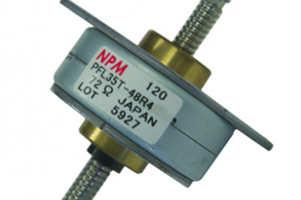
Jun 07, 2011
Providing engineers with the ability to design a linear motion system at a low cost and with simplicity, Nippon Pulse offers its PFL35T LINEARSTEP® tin-can type linear actuator. Nippon Pulse's LINEARSTEP series offers direct linear motion without the need of any mechanical transformers, allowing users the ability to design a simple system at a low cost.
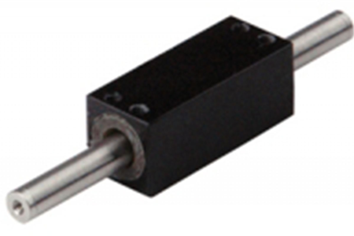
Apr 05, 2011
The Nippon Pulse Linear Shaft Motor is the first linear motor that is designed and constructed with the ultra high-precision market in mind. Because of its design features, the Linear Shaft Motor is more energy efficient and can achieve motion profiles similar linear motors are unable to achieve.
Mar 09, 2011
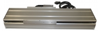
The Nippon Pulse SCR Nanopositioning linear stage series a high-precision, high-speed linear stage, that offers the accuracy of piezo stages, while maintaining the speed and performance of servo stages. Featuring the Nippon Pulse Linear Shaft Motor, the SCR stage series produces extremely accurate results with no loss in stability, regardless of the complexity of the motion profile.
Feb 21, 2011
Nippon Pulse has introduced the L160 Linear Shaft Motor, a tubular style linear servomotor. The L160 is the fourth release in Nippon Pulse's low maintenance L-series line, joining the L250, L320, and L427. The L-series motor features a larger non-critical air gap (up to 65%) than available on the standard S-series models.
Dec 08, 2010
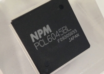
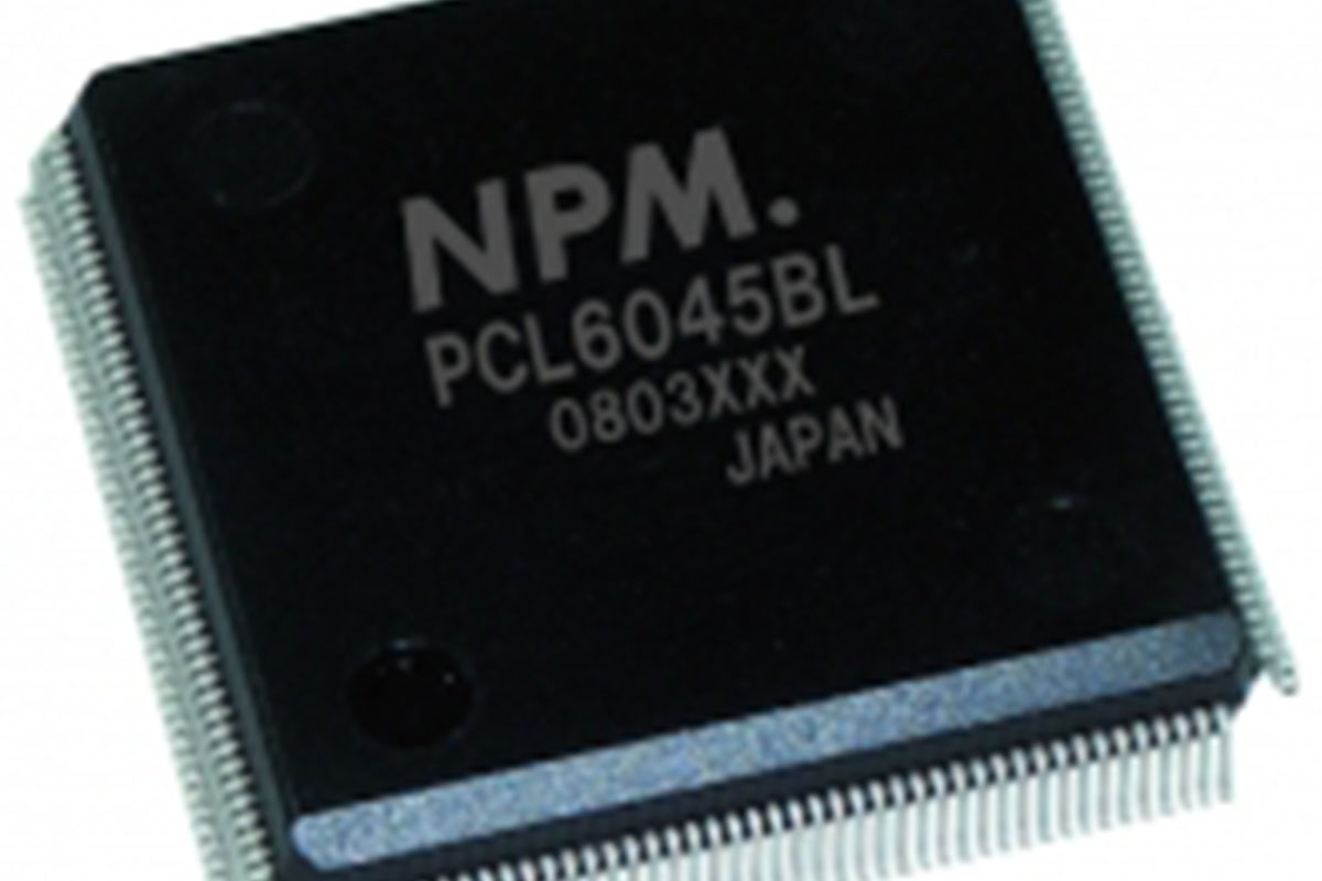
Nippon Pulse offers the PCL6045BL controller chip, a 4-axis programmable pulse generator that provides the oscillating, high-speed pulses to drive both stepper and servo (pulse string input types) motors. The PCL6045BL enables the user to easily configure complicated motion control systems.
Sep 02, 2010
Nippon Pulse introduces a new parallel option on its Linear Shaft Motor to simplify cable management and routing when using multiple motors with one encoder and one servo drive.
Jul 06, 2010
Nippon Pulse has announced the release of its newest linear servomotor, the L250SS Linear Shaft Motor. The new SS-series is highlighted by a forcer that is 50mm in length, significantly reducing the length that had been offered on the standard L250 motor. The standard L250 forcer length ranges from 120-210mm.
Jun 15, 2010
In its well established line of tin-can stepper products, Nippon Pulse offers its PF25G gearhead stepper motor. The PF25G motor is an ideal fit for projects within the medical device industry that require a high torque motor but are limited in available space.
Oct 29, 2009
Nippon Pulse America, Inc., (NPA), a leader in the motion control industry, is now offering its high precision SLP Acculine linear, single-axis stage series. The SLP stage has incorporated NPA's successful linear shaft motor into an all-inclusive stage that offers solutions for industrial applications.
Oct 22, 2009
Available from Nippon Pulse America, Inc., (NPA), a leader in the motion control industry, is an in-house model shop that offers 24-hour prototyping capabilities. The NPA model shop can add connectors and pinions to motors and also has the ability to prototype tin-can steppers, linear stepper motors, hybrid motors, controllers, and drivers to meet your individual need.